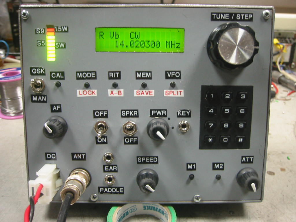
This three band CW transceiver uses a cheap DDS ( Ebay £3.50 ) for the VFO and a two pic DDS controller circuit. Primarily designed for holiday use this transceiver is small and light weight. Output power is 15 - 20 Watts on all bands ( although this is variable using the power control ), RX sensitivity is good for 1uV. Semi QSK is used, also a pic electronic keyer is included so a paddle can be used with the set.
The Pic controller circuit is by C.V. Niras ( VU3CNS ),source code is freely available on the Ham Radio India website. Version 4.1 is used in this build ( two Pic chips ).
The DDS controller circuit supports all amateur bands, although only three bands are utilised here due to space and complexity. The bands chosen for this set are 20m, 40m and 80m. Originally 10m was used, but i missed not having 80m so the build was modified for 80m. Any bands can be used, it is just a matter of using different component values for the band pass filters and the PA output filter.
In receive the signal enters the RF band pass filters via the antenna changeover relay and attenuator pot. Diode switches select the required band pass filter. A dual gate mosfet serves as a RF preamplifier to which AGC is applied to gate two. In transmit, the band pass filter and RF preamp are also utilised thus saving on components. The gate two voltage is used as a power control during transmit.
Following the RF pre-amp another dual gate mosfet is used as a receive mixer, the local oscillator from the DDS is injected into gate two. This is followed by a four pole crystal ladder filter. The crystals used in the filter are surplus CPU crystals, 4.9152 MHz and were selected for close matched parameters. Selectivity of the filter is very good indeed considering it has only four poles.
A two stage untuned cascode IF amplifier with AGC is used for IF amplification, IF output from this feeds a NE602 configured as a product detector. Demodulated audio is then fed to a buffer, audio band pass filter, another buffer and finally the audio PA using LM386. Sidetone is injected into the second audio buffer/mixer. Audio out from the first buffer is also fed to the AGC generator circuit.
Audio derived AGC is used here using full wave audio rectification thus halving the AGC time constant compared to half wave rectification. Although not as good as IF derived AGC, the AGC used here does work well.
A LED bar graph indicator is used for a S-meter and Pout indicator, A moving coil meter is preferable but none small enough were available at the time of build. No circuitry is shown here for this as it is pretty much a carbon copy of the manufactures data sheet ( LM3914 ). If you have a suitable moving coil meter I would advise using this as it is more accurate.
During transmit, another NE602 is used as a TX mixer, it's output is coupled to the required band pass filter by a step down RF transformer. Filtered and amplified TX signal is tapped off from the RF pre-amp and fed to the RF PA consisting of class A driver and two class AB push-pull stages. From here the signal is fed to the relevant low pass output filter via relays.
The set has been in use for several months and also used on a recent holiday, performance is very good although it does not look very pretty!
Here are a few pictures of the set
Here are the circuit diagrams of the set
RF Front EndBarry Zarucki M0DGQ
HOME